Introduction
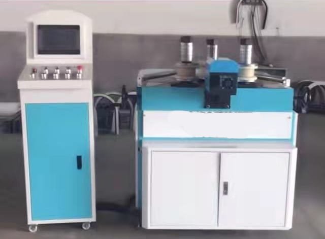
Hydraulic CNC rolling bending machines represent the pinnacle of metal forming technology, combining hydraulic power with computer numerical control to achieve precise circular bending of metal plates. These machines are widely used in manufacturing pipelines, pressure vessels, and structural components requiring high-precision curves.
Machine Components
- CNC Control System: The brain of the operation, featuring programmable logic controllers and touchscreen interfaces for parameter input.
- Hydraulic Power Unit: Provides the necessary force for bending operations, typically with pressure ranges between 10-30 MPa.
- Roller Assembly: Consists of three or four hardened steel rollers (top roller and side rollers) that apply progressive bending force.
- Support Structure: Heavy-duty frame designed to withstand bending forces up to several hundred tons.
Operation Procedure
1. Pre-Operation Preparation
- Machine Inspection: Verify hydraulic oil levels (ISO VG 46 recommended) and check for leaks in the hydraulic system.
- Tooling Setup: Install appropriate roller dies based on material thickness (common range: 3mm-50mm steel plates).
- Safety Check: Ensure emergency stop buttons and safety guards are functional.
2. CNC Programming
- Input material parameters (thickness, width, yield strength)
- Set target diameter (precision up to ±0.1mm achievable)
- Program bending sequence (typically 3-5 passes for full circular forming)
- Common CNC commands include:PlainText
G01 - Linear movement G02/G03 - Circular interpolation M08/M09 - Hydraulic clamp control
3. Material Loading
- Use overhead cranes for plates exceeding 50kg
- Align material edge with machine reference point
- Activate hydraulic clamps to secure workpiece
4. Bending Process
- Initial Bend: Top roller applies 10-20% of total pressure for first contact
- Progressive Forming: Side rollers move incrementally (0.5-5mm per pass)
- Final Closure: Hydraulic system applies maximum pressure for diameter calibration
5. Post-Processing
- Release hydraulic pressure gradually
- Remove formed component using vacuum lifters
- Measure final dimensions with laser scanners or templates
Advanced Features
- Automatic Compensation: CNC adjusts for material springback (typically 2-5° compensation)
- Multi-Axis Control: Modern machines offer 4-6 axis synchronization
- Database Integration: Stores parameters for common materials (Q235, SS304, etc.)
Safety Considerations
- Maintain safe distance (≥1m) during operation
- Never exceed machine capacity (marked on rating plate)
- Wear ANSI-approved protective equipment:
- Safety glasses (ANSI Z87.1)
- Steel-toe boots (ASTM F2413)
- Hearing protection (NRR 25dB+)
Maintenance Schedule
| Component | Frequency | Action |
|---|---|---|
| Hydraulic Oil | 500 hrs | Filter replacement |
| Roller Bearings | 1,000 hrs | Grease replenishment |
| CNC System | Weekly | Backup parameters |
| Hydraulic Hoses | Annually | Pressure testing |

Troubleshooting Guide
- Uneven Bending: Check roller alignment (tolerance ≤0.05mm/m)
- Hydraulic Issues: Verify pump pressure (typically 15-21MPa)
- CNC Errors: Reset system and reload backup program
Industry Applications
- Energy Sector: Pipeline fabrication (API 5L compliance)
- Construction: Structural arches (ASTM A36 materials)
- Transportation: Vehicle frame components
With proper operation, these machines can achieve production rates of 20-30 bends per hour for standard components, with dimensional accuracy meeting ISO 2768-mK standards. The combination of hydraulic power and CNC precision makes this equipment indispensable for modern metalworking facilities.
This guide covers all essential aspects of operating hydraulic CNC rolling bending machines while incorporating technical details from various machine manuals and industry standards. Would you like me to elaborate on any specific section?


